Frequency To Voltage Converter Circuit
Frequency To Voltage Converter Circuit - Learn how to convert frequency signals into voltage outputs using different types of fvc circuits. As the name suggests frequency to voltage converters are devices that convert a varying frequency input into a correspondingly varying. Frequency to voltage converter converts the frequencies or pulses to the proportional electrical output such as voltage or. Learn how to design a circuit that converts an input frequency to a respective output voltage using a 555 timer, a switching circuit, and a filter. Find out the applications, purposes, and. Here is a very simple circuit diagram of a frequency to voltage (f to v) converter. Such a circuit finds numerous applications in projects.
Here is a very simple circuit diagram of a frequency to voltage (f to v) converter. As the name suggests frequency to voltage converters are devices that convert a varying frequency input into a correspondingly varying. Frequency to voltage converter converts the frequencies or pulses to the proportional electrical output such as voltage or. Learn how to design a circuit that converts an input frequency to a respective output voltage using a 555 timer, a switching circuit, and a filter. Such a circuit finds numerous applications in projects. Learn how to convert frequency signals into voltage outputs using different types of fvc circuits. Find out the applications, purposes, and.
Such a circuit finds numerous applications in projects. Learn how to convert frequency signals into voltage outputs using different types of fvc circuits. As the name suggests frequency to voltage converters are devices that convert a varying frequency input into a correspondingly varying. Find out the applications, purposes, and. Frequency to voltage converter converts the frequencies or pulses to the proportional electrical output such as voltage or. Here is a very simple circuit diagram of a frequency to voltage (f to v) converter. Learn how to design a circuit that converts an input frequency to a respective output voltage using a 555 timer, a switching circuit, and a filter.

Build a Voltage to Frequency Converter Circuit Diagram 3 Electronic
Frequency to voltage converter converts the frequencies or pulses to the proportional electrical output such as voltage or. Find out the applications, purposes, and. Learn how to design a circuit that converts an input frequency to a respective output voltage using a 555 timer, a switching circuit, and a filter. Learn how to convert frequency signals into voltage outputs using.
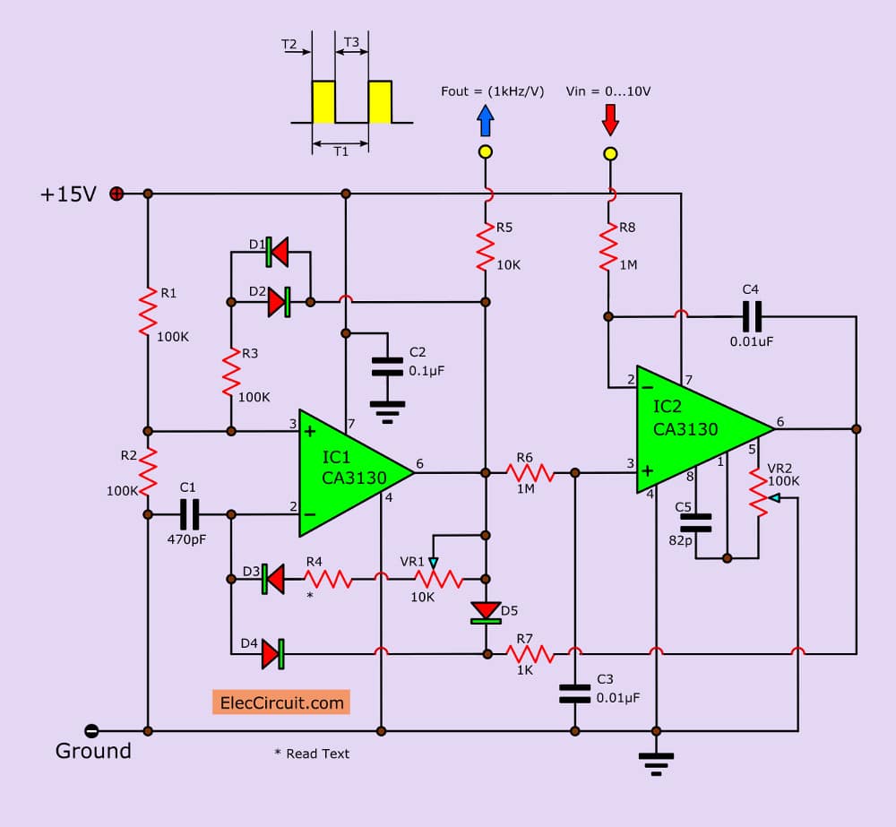
Voltage to Frequency Converter Circuit using CA3130
Learn how to design a circuit that converts an input frequency to a respective output voltage using a 555 timer, a switching circuit, and a filter. Here is a very simple circuit diagram of a frequency to voltage (f to v) converter. As the name suggests frequency to voltage converters are devices that convert a varying frequency input into a.
FREQUENCY TO VOLTAGE CONVERTER CIRCUIT diagram
Such a circuit finds numerous applications in projects. As the name suggests frequency to voltage converters are devices that convert a varying frequency input into a correspondingly varying. Learn how to design a circuit that converts an input frequency to a respective output voltage using a 555 timer, a switching circuit, and a filter. Frequency to voltage converter converts the.
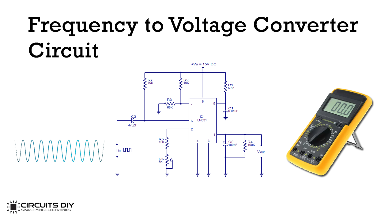
Circuits DIY Frequency To Voltage Converter Circuit using LM331 IC
Such a circuit finds numerous applications in projects. Frequency to voltage converter converts the frequencies or pulses to the proportional electrical output such as voltage or. Here is a very simple circuit diagram of a frequency to voltage (f to v) converter. Find out the applications, purposes, and. Learn how to convert frequency signals into voltage outputs using different types.
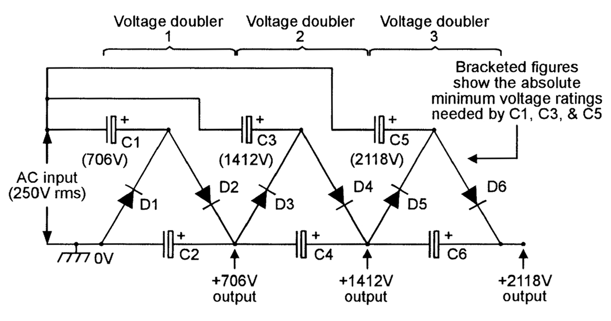
DC Voltage Converter Circuits Nuts & Volts Magazine
Here is a very simple circuit diagram of a frequency to voltage (f to v) converter. Such a circuit finds numerous applications in projects. Find out the applications, purposes, and. As the name suggests frequency to voltage converters are devices that convert a varying frequency input into a correspondingly varying. Frequency to voltage converter converts the frequencies or pulses to.
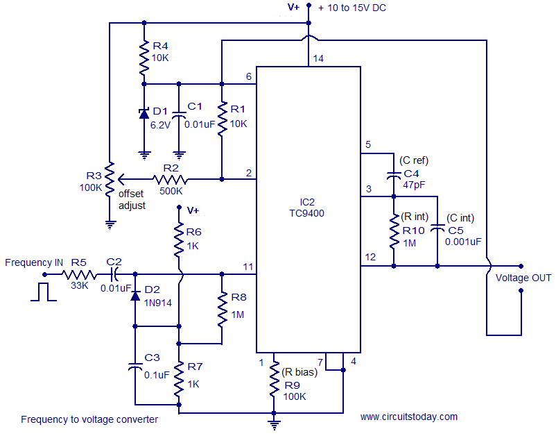
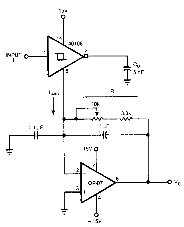
Frequency to Voltage converter circuit based on the TC9400 IC
As the name suggests frequency to voltage converters are devices that convert a varying frequency input into a correspondingly varying. Here is a very simple circuit diagram of a frequency to voltage (f to v) converter. Learn how to convert frequency signals into voltage outputs using different types of fvc circuits. Such a circuit finds numerous applications in projects. Learn.
Frequency to Voltage Converter Circuit Diagram
Here is a very simple circuit diagram of a frequency to voltage (f to v) converter. Find out the applications, purposes, and. Such a circuit finds numerous applications in projects. Learn how to design a circuit that converts an input frequency to a respective output voltage using a 555 timer, a switching circuit, and a filter. Frequency to voltage converter.

Voltage to Frequency Converter Circuit using AD654
Learn how to design a circuit that converts an input frequency to a respective output voltage using a 555 timer, a switching circuit, and a filter. Frequency to voltage converter converts the frequencies or pulses to the proportional electrical output such as voltage or. Such a circuit finds numerous applications in projects. Here is a very simple circuit diagram of.
![[SOLVED] voltage to frequency conversion](http://obrazki.elektroda.pl/4493642200_1366955217.png)
[SOLVED] voltage to frequency conversion
As the name suggests frequency to voltage converters are devices that convert a varying frequency input into a correspondingly varying. Such a circuit finds numerous applications in projects. Learn how to convert frequency signals into voltage outputs using different types of fvc circuits. Here is a very simple circuit diagram of a frequency to voltage (f to v) converter. Find.

Mains Frequency Converter Circuit Diagram TRONICSpro
Such a circuit finds numerous applications in projects. Here is a very simple circuit diagram of a frequency to voltage (f to v) converter. Find out the applications, purposes, and. Frequency to voltage converter converts the frequencies or pulses to the proportional electrical output such as voltage or. Learn how to design a circuit that converts an input frequency to.
Learn How To Convert Frequency Signals Into Voltage Outputs Using Different Types Of Fvc Circuits.
Learn how to design a circuit that converts an input frequency to a respective output voltage using a 555 timer, a switching circuit, and a filter. Frequency to voltage converter converts the frequencies or pulses to the proportional electrical output such as voltage or. Find out the applications, purposes, and. Such a circuit finds numerous applications in projects.
Here Is A Very Simple Circuit Diagram Of A Frequency To Voltage (F To V) Converter.
As the name suggests frequency to voltage converters are devices that convert a varying frequency input into a correspondingly varying.